An apology & get back to work.

•January 3, 2010 • 2 Comments

looks like finals and holidays got the best of me. I’ve been able to screw around here and there, but couldn’t spare any time to do any updating. Whatever.

I brought my crank over to Dan, my neighbor/machinist, who measured it out along with the main bearings. I can’t recall the figures now [that must have been over 1.5 months ago now!] but they were way out of spec and looked like hell anyway. I was able to source a crank and bearing set from a low mileage ambassador that Charles Mullendore [of antitem classic cycle]. Here’s a large picture with both cranks :

Along with the crank, I picked up the main bearings and rods too. The decision haunted me for awhile – used crank vs. regrind + undersized bearings. What really sealed the deal was my inability to source a decent used oil pump, the $364 price tag of a new one and a super fixed budget.

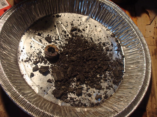
So, looks like all these parts are useless to me

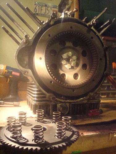
Add to this picture: clutch, clutch springs, valve guides, valve springs [decided to install heavier lemans springs because of the b10 cam], oil pressure relief valve*…. you get the idea.

*oil pressure relief valve
A little part I almost disregarded at first. The pressure relief valve is located in the hard oil line at the bottom of the case, right where it meets the sump. It’s job is to regulate the oil pressure, shutting off when pressure reaches a given amount. To test, you need to construct a tool capable of measuring pressure and one that also mates to the oil line. Since I don’t have a compressor and any of the required materials to make such an apparatus, I decided to mail it to Charles Mullendore who tested it out for me.

Charles: “Initial testing revealed that it leaked off pressure from 20 psi on up and never really “popped off”. Once apart it was easy to see why – the piston’s sealing surface looked like it had been ground on a bench grinder. Greg B. says he sees lots of them like that. Scary. I pulled a good piston from my stash of used parts and lapped the sealing surfaces thoroughly. Now it works as it should – very slight “bleed off” beginning at 50 psi and “pop off” at 62 psi.”

Me : “And jeez man, so it was bleeding off a really low psi – I’ve been trying to reason out what that would mean in terms of the running motor. Does that mean that I’ve been running with extremely low pressure then, since the valve couldn’t handle a strong psi?”

Charles: “That’s exactly what it means – you probably never had more that 30-40 psi at most, even less on hot days, in traffic, etc. Could be why the crank and cam were worn as much as they were.”

Looks like this tiny little part, which cost me $30 to have fixed [Charles Mullendore rules!] is responsible for much of the carnage I have experienced. Feels pretty good to know why things were so screwed up.

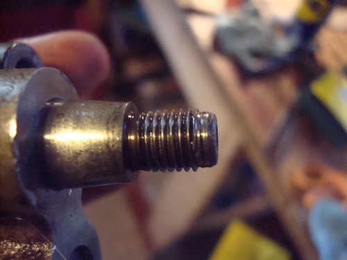
Another small hang up was the hardware. Maybe it’d been over torqued in the past or something with the heat cool cycles of a 40 year old engine, but 2 of the 5 main bearing bolts looked like this after I tried to install them

This was pretty exciting. I mean, steel bolts – aluminum casing…. I thought the threads would’ve ripped out before this happened. The 2 stretched bolts never accepted more than 16 ft/lbs. I ended up replacing them with new 8.8 grade bolts with schnoor washers instead of the locktabs which looked like they were about to snap anyhow.

Last lesson of 2009 : Don’t trust your bolts or your relief valves.


Balancing act.

•November 18, 2009 • 1 Comment

Deciding whether or not to balance the crank assembly has proven to be really difficult.
When everything is out and on your lap, it seems like a good opportunity. If my budget wasn’t all accounted for, I’d do it in a heartbeat – because why not? But, it is and I’ve got to figure for something cheaper.

So I thought to just statically balance the reciprocating parts, or just try to get both ‘sets’ as close to equal as I could…Sounded like the free option to me – Just some elbow grease, a file or dremel and a decent scale and I’d be in business.

So this morning I took the rods, pistons, rings, circlips and wristpins to school, snuck into the geology lab and used one of their [Ohaus] triple beam balances. I massed everything >3 times and used two different scales.

All the manual says on the subject is that conrods should be within 3g of each other, and pistons within 1.5g.
Here are my numbers that I came up with:

translation:

PISTON
a) 391.05
b) 390.08

RINGS
a) 34.32
b) 34.38

WRIST PINS
a) 95.65
b) 96.50

CIRCLIPS
a) 1.88
b) 1.89

RODS (minus bearings)
a) 503.84
b) 505.80

ROD NUTS AND BOLTS
a) 72.85
b) 73.20

You can see my rods are off by 2.04g – which is within reason. And the pistons are off by .97 – very kosher.

Then I juggled the numbers a little – add things up so the sums aren’t so far apart
After awhile I came up with this:

391.05         390.08
34.32         34.42
96.50         95.65
503.84          505.80
73.2               72.85
1.88              1.89
—————————————————————–
1100.79g             1100.69g

diffence of .10g!

Really quite insane. I probably won’t do anything further in the balancing department.

….. the following parts are in the mail. I guess nothing further is standing in the way of building the motor back up.

1 x distributor o ring Eld,Amb,V700
6 x Schnoor washer, 8mm
12 x cylinder stud o-ring, Viton, 12 per engine, 90706090
1 x distributor spring set, V700-Amb-Eldo, pair
1 x crankshaft plug, sludge trap
6 x flywheel bolt, hardened 10.9
2 x aluminum seal washer, 12mm
1 x oil pump, V7 V700 V750Special Ambassador and most Eldorado
4 x Lock plate for con rod nut, V700-Ambassador
1 x Gasket set Ambassador complete
1 x V700 civilian brake cable, no switch
4 x connecting rod bearing half shell, newest version
1 x Valve spring kit, 4 standard inners, 4 28037460 outers
1 x rear main seal, viton, directional, all big twins

Good parts vs. Bad parts

•November 10, 2009 • Leave a Comment

All I’ve been doing is cleaning, for the most part. It takes awhile to do this stuff by hand

– using scotch brite pads, wd40 and simple green – but works well.

I got my B10 cam in the mail along with some resurfaced cam followers.

Pictures of the old stock cam [above] and the B10 [below]

Stock [left] – B10 [right]

Worn old tappets [above] – resurfaced tappets [below]

I also had my neighbor/machinist resurface my rockers to get rid of that indent.

I’ve had several people tell me it was fine to just use a honing stone or emery cloth and was all set to do that, but my neighbor said it was a good idea to keep the plane of that surface parallel to the rotational axis. Who is right? I don’t know, and was only charged a hamburger for the services rendered.

My old busted oil pump

•October 29, 2009 • Leave a Comment


MOV01890

Originally uploaded by getonyourbikesandride

Crunching those threads on the end of my oil pump was a blessing in disguise. If I hadn’t done that, I wouldn’t have brought them over to my neighbors [who doubles as my machinist] to ask him about his opinion on the best fix.

Turns out the thing is pretty well worn out all around. I tired to show the various degrees of play the gears have, and at the end you can see the teeth have all worn a substantial taper – all this adds up to a pump not working to capacity [although my oil pressure light never came on].

This will definitely be replaced.

crank and bearings

•October 27, 2009 • Leave a Comment

The crank was pulled last, after the con rods were removed. There were a few nicks here and there, but I still don’t know what its fate will be since I have yet to have it measured.

This is the section of the crank that mates with the rear carrier bearing. This seems like the most worn section.

and the rear carrier. Pretty worn if you ask me, a pretty good divot shown in this picture.

and the front carrier still attached to the block. You can see some worn grooves here too.

These old motors don’t have oil filters, besides a crude centrifugal sludge trap located in the center of the crank, which traps sediment inside. I guess its better than nothing, but if this sludge accumulates too much there is a major risk of blocking the oilways and starving the con rod big end bearings.

Here is a picture of the sludge I found in my crank. Ghastly.

Most of it removed.

And now we’re all caught up to date.

cam and cam followers

•October 26, 2009 • Leave a Comment

With the gears off, the cam thrust bearing and cam are an easy removal.
I was pretty surprised the cam doesn’t run in a replaceable bearing, like the crank does.

The lobes are a little worse for wear.
Each lobe has the identical wear marks

By now I think it’s pretty obvious the mileage indicated on the odometer when I received the bike wasn’t very accurate, unless the PO was a POS. I could maybe possibly have this reground, but a fellow loopframer offered to sell me a B10 cam and resurfaced lifters.

About the B10 cam (from mgcycle.com)

These cams provide a noticeable seat of the pants power boost at all rpms without straining the valve gear or other engine components. Among the best bang for the buck improvements. The B10 grind made it’s debut in the “Powering Up Kit” offered for the early LeMans models, and was later used as original equipment in the LeMans 1000 series, as well as in a few 1000S and California III models.

The cam followers are removed from the large holes left and right of the 12 o’clock cylinder stud.

And here is a shot of my worse worn cam follower.


This is the face that rides the cam, the push rod is inserted into the other end.
I’m told ones nicer than this are thrown out and not even considered to be resurfaced, and that this one probably was oil starved, or a piece of debris (chrome!) was between the cam lobe and the follower’s face.

inner timing cover

•October 26, 2009 • Leave a Comment

Back to the front.

With the inner timing cover off, I got my first view of the helical cut gears.

The front main seal (still attached to the cover on the bottom right) has been weeping for months, have been looking forward to fixing that leak for some time.

I found these crude drain holes a little offsetting, but I guess all they are doing is allowing the oil to drain faster back into the sump. I’ve been told not to pay them much mind.

With the gears off you can see the camshaft [top], crank shaft [middle] and the oil pump on the bottom, each driven by their own gear.

The oil pump is that small square on the bottom and its gear attached to the small bolt that protrudes out. This was the only gear that required the use of a puller – I wished I thought to examine my puller before I went at it. My puller in particular [a harbor freight model] uses a hollow main bolt, which I really never noticed before. When I placed it over the oil pump bolt, it slipped down over it and buggered the leading thread. I subsequently put a large washer between the puller and the bolt to get the gear off. I think the pump bolt is repairable, well I really hope it is because a replacement pump is over $300.

I’m hoping I can just run a die over it.

ring gear, clutch and flywheel

•October 26, 2009 • Leave a Comment

My ring gear had suffered some wear due to a faulty starter solenoid, which was providing a short throw to my starter’s bendix. This resulted in poor starter engagement, and a ton of terrible grinding noise. All of the teeth on my ring gear (gear which the starter grabs to turn the motor over) where chewed down 1/8″ by the starter.

One of the first fixes I did back in 2007 was to replace the solenoid with a new and correct one from MG cycle. Instant fix too, perfect engagement every time. Although the damage to my ring gear had already been done, the engagement has not suffered since, and I’ll just reuse the ring gear when the motor gets put back together.

The ring gear and clutch came off next.

What’s funny about this picture is that I thought I had the clutch pack completely out of the mill. Still secured in the flywheel was the pressure plate and springs, which one would think would want to pop itself free due to the spring force pushing it out. However, the amount of friction material in the splines of the flywheel bound the plate in place and prohibited complete movement. It actually took me to clean the friction material out of the splines with a flat head and some judicial prying to free the plate. And now I no longer wonder why my clutch wouldn’t properly disengage all the time.

Some may measure out their plates and decide to reuse them or not. Personally I’m just going to replace them as I’m a firm believer of “while you are in there.”

Here is the pressure plate removed. Only the flywheel remains.

And with the flywheel removed.

This is supposed to be a dry cavity and any oil you see is either from the rear main seal or the cam shaft plug seal. I’ll replace the main seal and seal the cam plug with JB weld.

pistons and cylinders

•October 26, 2009 • Leave a Comment

With the juggs and pistons off……

You can see some scoring on this piston to the right of the wrist pin. This is the left side of the engine, the side with the noticeable ‘clank’.

I believe this to be caused by chrome flakes, but cannot say for sure. I have already purchased a new set of Gilardoni cylinders and pistons from MG cycle, so I wasn’t too concerned with the condition of my old ones.

And one more point of interest is my small end bushings – particularly on the right side, which fell out under its own weight! Here you can see it inching its way out of the con rod. These are supposed to be a tight interference fit, so yeah – this is another bad sign.

rocker wear.

•October 26, 2009 • Leave a Comment

When I first brought my bike home, the first thing I did was pull the heads to check and see what was going on with my cylinders. I don’t think you can own or be in the market for a guzzi of this era and not know of the potential damage failing chrome liners can do.

I found out quickly enough that I had iron sleeved liners, and was happy enough to leave it at that. I put the heads back on and put a few thousand miles on the bike the next 2 years. I change my oil probably more than some would think necessary (at or before every 1,200 miles) and I’ve dropped the pan for a cleaning twice. Still, the remnants of those cursed chrome liners are found in every little crevice of my block. Here you can see a tiny flake blocking the oil passage way in my rocker spindle.

Surprisingly, it did not fail. Though I’m still not sure if I am going to ruse the part.

One more subject of discussion in the cylinder head area is the wear on the rocker arm where it makes contact with the valve stem. It’s probably best to show the picture first so we are on the same page.

Now you can see where the valve stem makes contact with the rocker and created this little divot. While still structurally sound, the problem is that this induces an incorrect measurement when using a feeler gauge to set the valves. The feeler gauge will measure between the high spot on the rocker and the valve stem and will be loose to the degree of that divot. Considering these clearances are to a hundredth of a millimeter, I’m going to sand or hone these down to remove this depression.